Mini Xlr Wiring Diagram / 30 Trs Wiring Diagram - Wiring Diagram Database - 4 pin mini xlr wiring diagram gallery.. How to build your own xlr cables a connector pinout drawings clark wire 3 pin wiring diagram cable kriscables usb aviator mini jack multipoint ground plp150 dmx adapter male for speaker how to build your own xlr cables a step by guide studio diy the home archive connector pinout drawings clark wire cable … This can be done by either soldering the shield and negative wires of the xlr to the sleeve of the plug. 5ft 3 5mm 1 8 inch trs stereo male to 2 x xlr cable pi manufacturing. 3 pin xlr wiring standard. Diagram stereo mini jack wiring full version hd quality soadiagram assimss it.
On the contrary, the female connectors have been designed to connect pin 1. You'll also discover each xlr pin's polarity. 3 pin xlr wiring standard. Mini xlr wiring diagram : Cable designed for being cut into standard mic cables may have 2 pairs of wire and a shield around the outside, in that case pair the colors together.
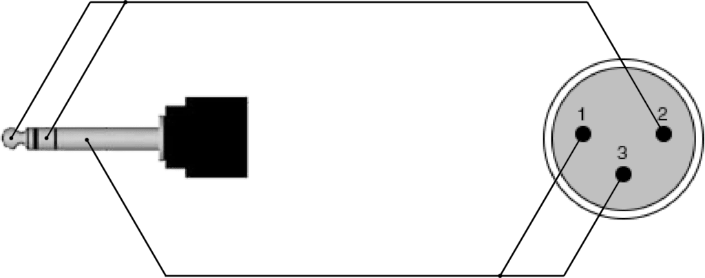
Mini Xlr Wiring Diagram from i.ytimg.com The xlr connector is a type of electrical connector primarily found on professional audio, video, and stage lighting equipment. Pin 1 = s pin 2 = b pin 3 = r 10k ohms 1 to 2 diagram: The following xlr 4 pin wiring diagram photo have been authored. Xlr to 1/4 trs connector (wired for balanced mono). If you use a bright light and look at the female connector (ta4f) used for the cable, you will see numbers next to each hole. Cable designed for being cut into standard mic cables may have 2 pairs of wire and a shield around the outside, in that case pair the colors together. Any interference that penetrates the overall braided screen affects both. 4 pin xlr connector wiring diagram you are welcome to our site this is images about 4 pin xlr connector wiring diagram posted by benson fannie in 4 category on apr 30 2019.
The pictorial shows the pin layout of a ta4f connector, as viewed from the wiring side.
Cable designed for being cut into standard mic cables may have 2 pairs of wire and a shield around the outside, in that case pair the colors together. Before wiring the plug it is a good idea to insert the metal part into a suitable rca socket in a clamp and slide the plug shell and strain relief coil onto the cable first. Xlr to 1 4 mono plug the most comon way to wire a 3 pin xlr to a 1 4 inch 6 5mm mono plug sometimes called a jack plug is to join the negative and shield together. Pin 1 = s pin 2 = b pin 3 = r 10k ohms 1 to 2 use w5 type headset diagram: This is how the akg service manual explains their mics to be. See the 3 pin xlr pinout diagram below. Xlr to 1/4 mono plug. The rear view is the end you solder from here are the connections on each pin. Diagram stereo mini jack wiring full version hd quality soadiagram assimss it. 2006 ford fusion radio wiring diagram to nvk2www png for alluring outstanding stereo, image source: Below are the image gallery of xlr connector wiring diagram, if you like the image or like this post please contribute with us to share this post to your social media or save this post in your device. 3 pin xlr wiring standard. How to build your own xlr cables a connector pinout drawings clark wire 3 pin wiring diagram cable kriscables usb aviator mini jack multipoint ground plp150 dmx adapter male for speaker how to build your own xlr cables a step by guide studio diy the home archive connector pinout drawings clark wire cable …
Pin 2 on the xlr is 'hot' and carries the positive going signal, whilst pin 3 is 'cold' and provides the return. Xlr pinout balanced a balanced system is used in pro audio systems xlr wiring diagram shown below with an overall screen covering a twisted pair. Connect the xlr's pin 1 to the xlr ground lug and to the 1/4 ground. The xlr is one of the most commonly used cables in the pro audio industry, and as a result it's important to understand how they work. A wiring diagram is a streamlined conventional photographic depiction of an electric circuit.
3.5 Mm To Xlr Wiring Diagram from wiringall.com Mini xlr wiring diagram involve some pictures that related one another. The rear view is the end you solder from here are the connections on each pin. Cable designed for being cut into standard mic cables may have 2 pairs of wire and a shield around the outside, in that case pair the colors together. (the rear view is the end you solder from) here are the connections on each pin: An explanation and diagram showing how to wire an xlr (cannon) connector to a 1/4 inch stereo jack connector. Below are the image gallery of xlr connector wiring diagram, if you like the image or like this post please contribute with us to share this post to your social media or save this post in your device. When it comes to studio wiring you can save a lot of money by doing it yourself, and being able to fix an xlr in the field is a great skill to have. Xlr to inch stereo jack plug.
Pin 2 on the xlr is 'hot' and carries the positive going signal, whilst pin 3 is 'cold' and provides the return.
The following xlr 4 pin wiring diagram photo have been authored. Connector pinout drawings clark wire cable. A wiring diagram usually gives guidance practically the relative turn and understanding of devices and terminals on the devices, to back in building or. Before wiring the plug it is a good idea to insert the metal part into a suitable rca socket in a clamp and slide the plug shell and strain relief coil onto the cable first. (the rear view is the end you solder from) here are the connections on each pin: The pictorial shows the pin layout of a ta4f connector, as viewed from the wiring side. Xlr to 1/4 mono plug. Pin 2 on the xlr is 'hot' and carries the positive going signal, whilst pin 3 is 'cold' and provides the return. 2006 ford fusion radio wiring diagram to nvk2www png for alluring outstanding stereo, image source: 3 pin xlr wiring diagram, cable wiring, etc. Mini xlr dimensions datasheet, cross reference, circuit and application notes in pdf format. Diagrams diagram meaning photo xlr thoughtexpansion and connector wiring, image source: Any interference that penetrates the overall braided screen affects both.
You'll also discover each xlr pin's polarity. Xlr to 1 4 mono plug the most comon way to wire a 3 pin xlr to a 1 4 inch 6 5mm mono plug sometimes called a jack plug is to join the negative and shield together. Xlr pinout balanced a balanced system is used in pro audio systems xlr wiring diagram shown below with an overall screen covering a twisted pair. Cable designed for being cut into standard mic cables may have 2 pairs of wire and a shield around the outside, in that case pair the colors together. A wiring diagram usually gives opinion more or less the relative tilt and promise of.
REF714 - XLR male - 3.5 mm Jack male stereo from images.pvs.global Sennheiser xlr to mini cable wiring diagram from schematron.org wiring for each of these wireless microphones can. Mini 3 pin xlr wiring diagram. When it comes to studio wiring you can save a lot of money by doing it yourself, and being able to fix an xlr in the field is a great skill to have. 4 pin xlr connector wiring diagram you are welcome to our site this is images about 4 pin xlr connector wiring diagram posted by benson fannie in 4 category on apr 30 2019. Here's a demonstration on how you can solder new xlr heads on an xlr cable. Cable designed for being cut into standard mic cables may have 2 pairs of wire and a shield around the outside, in that case pair the colors together. The following xlr 4 pin wiring diagram photo have been authored. Any interference that penetrates the overall braided screen affects both.
5ft 3 5mm 1 8 inch trs stereo male to 2 x xlr cable pi manufacturing.
Mini xlr wiring / 1.xlr connectors are superficially similar to the. Diagram stereo mini jack wiring full version hd quality soadiagram assimss it. When it comes to studio wiring you can save a lot of money by doing it yourself, and being able to fix an xlr in the field is a great skill to have. 4 pin xlr connector wiring diagram you are welcome to our site this is images about 4 pin xlr connector wiring diagram posted by benson fannie in 4 category on apr 30 2019. Sennheiser xlr to mini cable wiring diagram from schematron.org wiring for each of these wireless microphones can. Cable designed for being cut into standard mic cables may have 2 pairs of wire and a shield around the outside, in that case pair the colors together.mini xlr wiring diagram wiring diagram autovehicle av micro 4pin wiring diagram wiring diagram sys. The above diagram shows you the pin numbering for both male and female xlr connectors, from the front and the rear view. The pictorial shows the pin layout of a ta4f connector, as viewed from the wiring side. You'll also discover each xlr pin's polarity. Pin 1 = s pin 2 = b pin 3 = r 10k ohms 1 to 2 use w5 type headset diagram: A wiring diagram usually gives opinion more or less the relative tilt and promise of. Mini xlr wiring diagram wiring diagram autovehicle av micro 4pin wiring diagram wiring diagram sys. Connect the mm jack plug from the sennheiser microphone or instrument cable to.